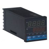
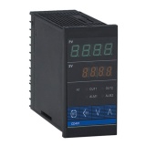
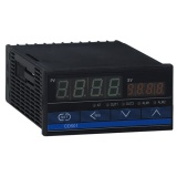
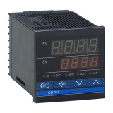
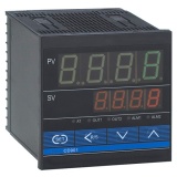
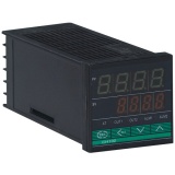
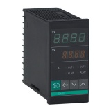
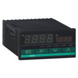
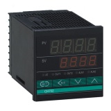
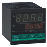
Temperature Controller CD series
• Industrial standard microcomputer processor
• Auto adjusting function
• Big screen LED display
• Heating/Cooling control
Product Features:
• Input: Universal input, support 10 different types of thermocouples and RTD inputs by customers selected at panels.
• Available for TWO groups Output of heating and cooling control
• Display temperature in Celsius (°C)
• Control precision: +/- 0.2%
• Control mode: PID, ON/OFF
• Control Output: Relay contact (3A @ 240 VAC), Voltage impulse output for external SSR, Current 0-20mA, 4~20 mA, Voltage 0-5V,0-10VDC
• Alarm: AL1 or AL2, 7 kinds of alarm mode: high/low/high deviation/low deviation/interval/out of interval/breakage alarm.
• Power Supply: 100~240V AC 50/60Hz, DC24V, or other voltage according your order.
Model Description and Model Selection:
|
CD/CH |
□ |
01/02 |
□ |
□ |
□ |
- |
□ |
□ |
* |
□ |
□ |
- |
□ |
□ |
|
|
① |
|
② |
③ |
④ |
|
⑤ |
⑥ |
|
⑦ |
⑧ |
|
⑨ |
⑩ |
|
①Outline dimension |
See the outline dimension picture |
||
|
②Control Mode |
F:PID operation and auto calculating (reverse operation) |
D:PID operation and auto calculating(Forward operation) | |
|
W: heating/cooling PID operation and auto calculating(cooling water)*1 |
A: heating/cooling PID operation and auto calculating(cooling wind)*1 | ||
|
③Input mode |
Refer to Input Range Table |
| |
|
④Range Code |
Refer to Input Range Table |
| |
|
⑤First control output(OUT1) (Heating side) |
M: Relay contact output |
8: Current output(IC4-20mA) | |
|
V: Voltage impulse output |
G: Thyratron driving & triggering output | ||
|
T: Thyratron output |
| ||
|
⑥Second controloutput( OUT2) (Cooling side)*2 |
No mark: when the control mode is F or D |
| |
|
M: Relay contact output |
T: Thyratron output | ||
|
V: Voltage impulse output |
8: Current output(IC 4-20mA) | ||
|
⑦First alarm (ALM1) ⑧Second alarm (ALM2)*2
|
N: no alarm |
| |
|
A: Upper-limit deviation alarm |
J: lower-limit input alarm | ||
|
B: Lower-limit bias alarm |
K: Standby upper-limit input alarm attached | ||
|
C: Upper/lower limit bias alarm |
L: Standby lower-limit input alarm attached | ||
|
D: alarm in area |
P: Heater line breakage alarm(CTL-6)*3 | ||
|
E: Standby upper-limit bias alarm attached |
S: Heater line breakage alarm(CTL-12)*3 | ||
|
F: Standby lower-limit bias alarm attached |
R: Control line breakage alarm *4 | ||
|
G: Standby upper/lower limit bias alarm |
V: Upper-limit setting alarm | ||
|
H: Upper-limit input value alarm |
W: Lower-limit set value alarm | ||
|
⑨Communication |
N: No communication |
| |
|
⑩Water-proof/dust-proof |
N: no water-proof/dust-proof |
| |
|
Note: *1 W or A type has no auto adjust function. *3 can’t be set First Alarm |
*2 Second alarm output(OUT2) Second alarm(ALM2) *4 Control ring line breakage can choose one only from Alarm1 and Alarm2 | ||
The Input Range Table:
|
|
Code |
Input Range |
Code |
Input Range |
Code |
Input Range | |||
|
Themocouple Input(TC) |
K |
K01 |
0-200°C |
K02 |
0-400°C |
K03 |
0-600°C | ||
|
K04 |
0-800°C |
K05 |
0-1000°C |
K06 |
0-1200°C | ||||
|
K07 |
0-137 2°C |
K13 |
0-100°C |
K14 |
0-300°C | ||||
|
| |||||||||
|
J |
J01 |
0-200°C |
J02 |
0-400°C |
J03 |
0-600°C | |||
|
J04 |
0-800°C |
J05 |
0-1000°C |
J06 |
0-1200°C | ||||
|
| |||||||||
|
R *1 |
R01 |
0-1600°C |
R02 |
0-1769°C |
R04 |
0-1350°C | |||
|
S *1 |
S01 |
0-1600°C |
S02 |
0-1769°C |
|
| |||
|
B *1 |
B01 |
400-1800°C |
B02 |
0-1769°C |
|
| |||
|
E |
E01 |
0-800°C |
E02 |
0-1000°C |
|
| |||
|
N |
N01 |
0-1200°C |
N02 |
0-1300°C |
|
| |||
|
| |||||||||
|
T *2 |
T01 |
0-350°C |
T02 |
-199.9-100.0°C |
T03 |
-199.9-200.0°C | |||
|
T04 |
-199.9-400.0°C |
|
|
|
| ||||
|
| |||||||||
|
RTD Input |
PT100 |
D01 |
-199.9-649.0°C |
D02 |
-199.9-200.0°C |
D03 |
-199.9-50.0°C | ||
|
D04 |
-100-100.0°C |
D05 |
-100-200.0°C |
D06 |
0.0-50.0°C | ||||
|
D07 |
0.0-100.0°C |
D08 |
0.0-200.0°C |
D09 |
0.0-300.0°C | ||||
|
D10 |
0.0-500°C |
|
|
|
| ||||
|
| |||||||||
|
JPT100 |
P01 |
-199.9-649.0°C |
P02 |
-199.9-200.0°C |
P03 |
-199.9-50.0°C | |||
|
P04 |
-100-100.0°C |
P05 |
-100-200.0°C |
P06 |
0.0-50.0°C | ||||
|
P07 |
0.0-100.0°C |
P08 |
0.0-200.0°C |
P09 |
0.0-300.0°C | ||||
|
P10 |
0.0-500°C |
|
|
|
| ||||
|
| |||||||||
|
Voltage Input |
0-5V |
401 |
0.0-100°C |
|
|
|
| ||
|
1-5V |
601 |
0.0-100°C |
|
|
|
| |||
|
Current Input |
0-20mA |
701 |
0.0-100°C |
|
|
|
| ||
|
4-20mA |
801 |
0.0-100°C |
|
|
|
| |||
|
Note: *1 The accuracy can not be guaranteed in 0-399°C *2 The accuracy can not be guaranteed in -199.9-100°C | |||||||||


